Ethernet cables remain the fastest and most reliable form of computer networking. Cables are cheap, but often you’ll need a different cable length than what’s available off the shelf.
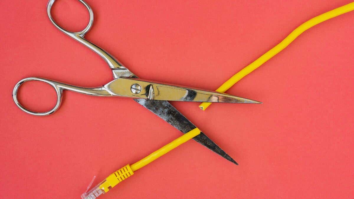
By “splicing” an Ethernet cable, you can give it a custom length, join two cables together, and even repair damage to a cable or the plugs at either end.
Understanding Ethernet Cable Basics
First, let’s get familiar with the nomenclature. Ethernet network cables (sometimes called just “network cables”) come in several varieties. The most common types for home use on Amazon or in any tech store are Cat5, Cat5e, Cat6, and Cat6a. They represent different iterations of cable technology that improve data transfer speed and reliability.
The ‘Cat’ part stands for ‘Category.’ Cat5e is an enhanced version of the basic Cat5 cable. Cat 5e and Cat6 provide gigabit speeds, and Cat6a can offer 10 gigabit speeds over shorter distances. Cat6a can support 10 Gbps up to 100 meters, while Cat6 can only do so up to 55 meters. The type of cable you’re working with will determine your data transfer speed and affect your internet connection and local network connection performance.
You’ll find a bundle of tiny, twisted pair conductors at the heart of an Ethernet cable. These conductors are color-coded wires that allow data transference from one end of the cable to the other.
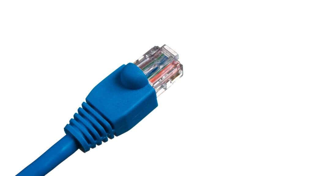
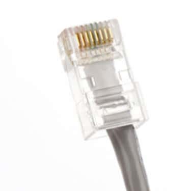
Each end of an Ethernet cable typically has an RJ45 plug. This plug, which looks like a larger telephone jack, is the part that physically connects to your devices, such as a router or a computer. The plugs you find on telephone lines are RJ11.
Tools of the Trade
To splice an Ethernet cable, you’ll need a few essential tools:
- Wire cutters
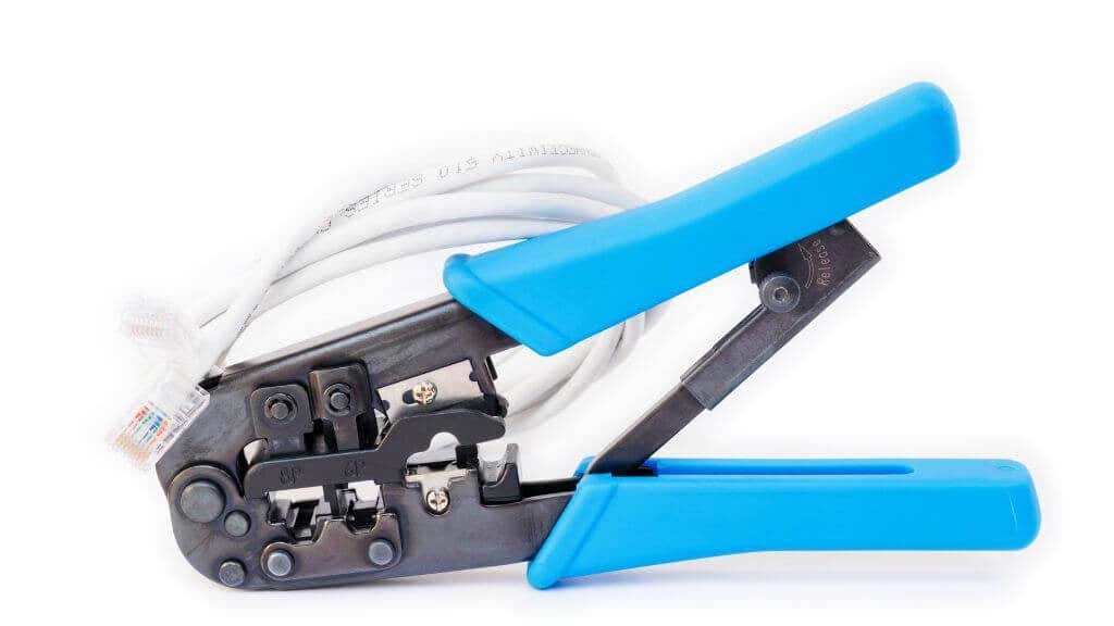
- Crimping tool
- RJ45 connectors
- Ethernet cable (the one you want to splice)
- Cable strippers
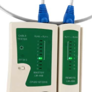
For testing the connections, you should get a network cable tester. This little device will let you know whether the connections in your newly spliced cable are working correctly. You can go ahead without the cable tester, but it just means you’ll only know if your cable has been spliced correctly when you plug it in.
You can get everything you need by purchasing a crimping tool kit, which includes wire cutters. Also, many crimping tools have integrated wire strippers so you don’t need to pay a separate one.
Step-by-step Guide: How to Splice Ethernet Cables
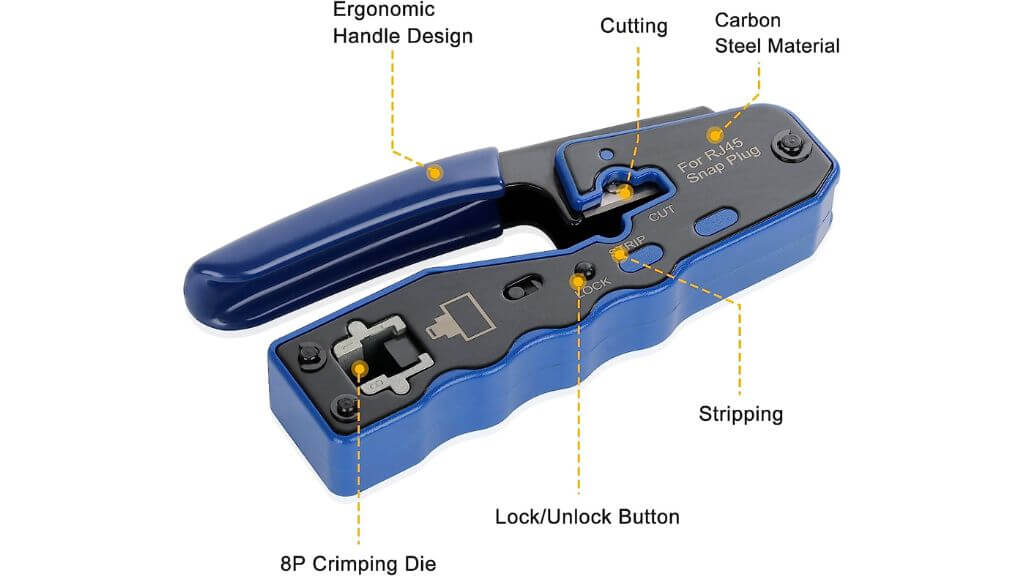
Splicing a cable can be finicky work, but it’s easy if you’re patient and careful. Here are the general steps to follow.
Step 1: Prepare Your Cable
First, use your wire cutters to trim off any damaged ends of the Ethernet cable. You want clean, undamaged wires to work with.
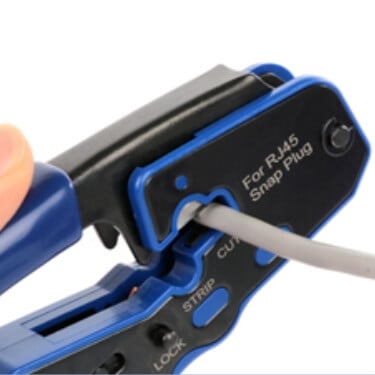
Use your cable strippers to carefully strip away about 2 inches of the outer casing at each end of the cable, revealing the color-coded twisted pair conductors inside.
Step 2: Unwind the Twisted Pair Conductors
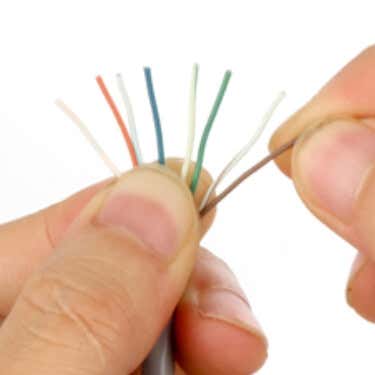
Carefully unwind the color-coded twisted pair conductors.
You’ll typically find eight wires in four pairs. Align them according to the Ethernet cable color code.
The standard color code for T568A wiring is:
⦁ Pin 1: White/Green
⦁ Pin 2: Green
⦁ Pin 3: White/Orange
⦁ Pin 4: Blue
⦁ Pin 5: White/Blue
⦁ Pin 6: Orange
⦁ Pin 7: White/Brown
⦁ Pin 8: Brown
The standard color code for T568B wiring is:
⦁ Pin 1: White/Orange
⦁ Pin 2: Orange
⦁ Pin 3: White/Green
⦁ Pin 4: Blue
⦁ Pin 5: White/Blue
⦁ Pin 6: Green
⦁ Pin 7: White/Brown
⦁ Pin 8: Brown
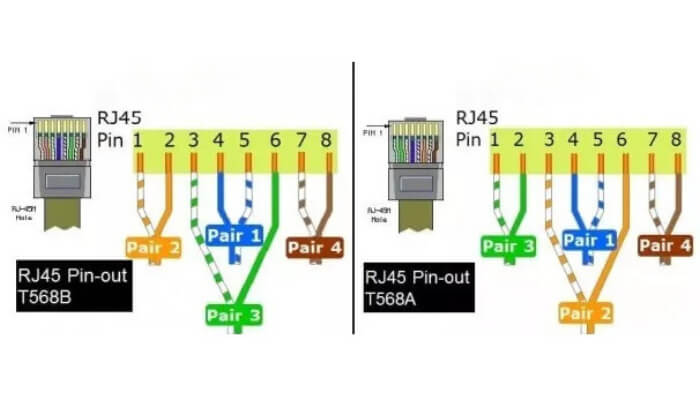
The most common scheme is T568B, but you can use either if you use it consistently. The cable you’re splicing probably uses T568B, the preferred wiring scheme for new network installations in the USA.
Many crimping tools have these wiring guides printed on the tool’s body, so you don’t have to memorize them.
Step 3: Attach RJ45 Connectors
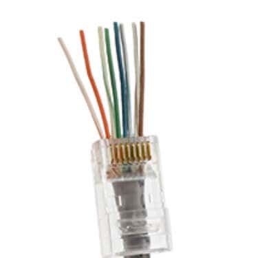
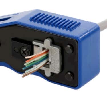
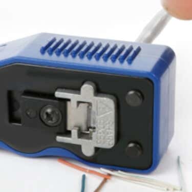
The next step involves attaching new RJ45 connectors to each cable end. Use your crimping tool to secure the connectors onto the cable.
Ensure the color-coded wires are lined up correctly inside the connectors before crimping. This is crucial for maintaining a solid internet connection.
This is just a general description of the process, you must follow the instructions of your specific crimping tool. Some may even come with a link to a full video demonstrating how to use them. We strongly suggest watching any such video if provided.
Step 4: Test Your Connection
Once the RJ45 connectors are in place, use your network cable tester to ensure the correct connections. Each light on the tester corresponds to a wire in the Ethernet cable. If all the lights light up, congrats! You’ve successfully spliced your Ethernet cable.
If you don’t have a cable tester, connect the cable to a pair of network devices. The best option is to connect a client device (i.e., a laptop) to a router. The cable is good to go if the connection works, and you can install it.
Advanced Splicing Techniques
The above method is the simplest way to splice an Ethernet cable, suitable for shorter lengths and non-critical connections. However, more advanced techniques are required when you need to join two cables over a longer distance or when working with more specialized types of cables, such as coaxial or fiber optic.
Patch Panels: Organizing and Future-Proofing
A patch panel is another advanced method used when multiple Ethernet cables need to converge. This can typically be found in office settings or advanced home networks. Patch panels are designed with several ports to accommodate multiple patch cables.
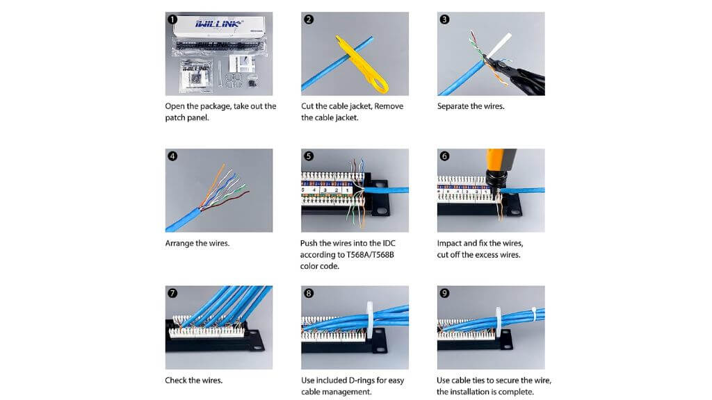
The process here involves terminating the ends of your Ethernet cables onto the rear of the patch panel. The front side, in turn, is used for patching data to where it needs to go using patch cords. The great thing about patch panels is that they make it easier to manage complex cable arrangements and are adaptable for future changes or additions.
Patch panels are reminiscent of old telephone switchboard junction boxes, where operators physically connect lines using short patch cords.
Using Keystone Jacks and Couplers
A keystone jack is a snap-in package that houses an RJ45 connector. These jacks can be snapped into a wall plate or patch panel, creating a permanent, secure connection.
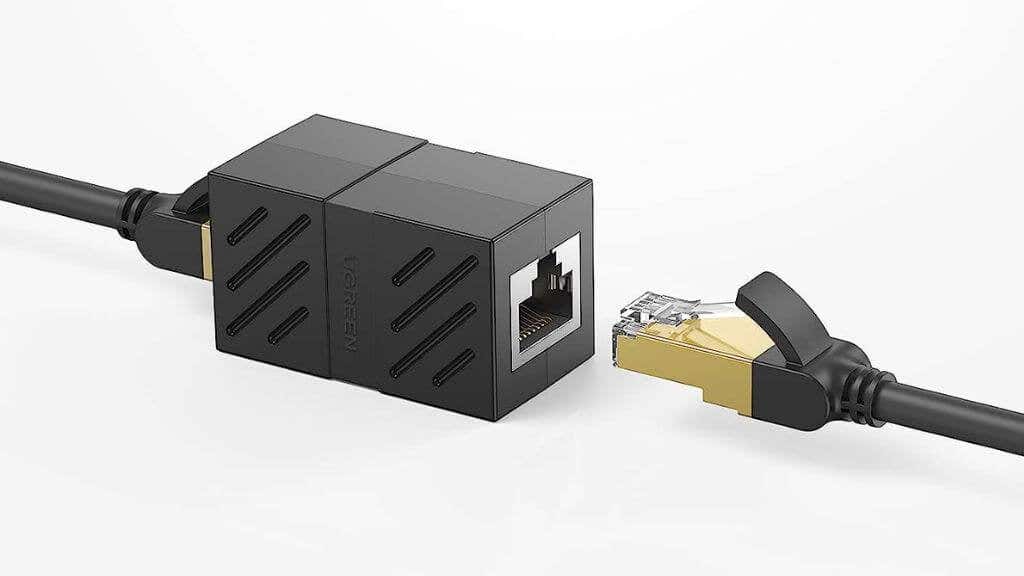
Couplers, on the other hand, are used to connect two Ethernet cables directly. They come with female RJ45 ports on both ends. Although couplers may not be the best solution for high-performance networks due to potential signal loss, they are handy for quick fixes or extending the range of an existing cable in non-critical applications. For example, if you want to connect a smart TV or NAS at home, you are okay with a slightly slower connection.
Direct Splicing of Ethernet Cables Without a Coupler
While a coupler provides a convenient way to connect two Ethernet cables, you can also splice them directly without a coupler. However, direct splicing requires much more attention to detail and dexterity. You’ll need a solid hand, basic soldering skills, and a soldering iron!
The steps are essentially the same as basic splicing, but things are different after you’ve stripped and unwound all eight of the wires on both ends you want to splice together.
Once the wires are unwound and aligned, twist the corresponding color-coded wires from each cable. Be sure that each wire from one cable is tightly twisted with its counterpart from the other cable. This ensures a secure connection and accurate data transmission.
After twisting the wires together, apply some solder to each connection. Soldering strengthens the splices and provides better conductivity, ensuring minimal signal loss. Be sure to use an appropriately sized soldering iron and avoid over-soldering, which could cause short circuits.
Once you’ve soldered all the connections, it’s time to insulate them. Wrap each connection individually with electrical tape to prevent any short circuits. After wrapping each splice, you can combine the whole group to form a single cable. Electrical tape isn’t a permanent solution, so you might want to invest in heat shrink insulation instead.
Dealing with Coaxial and Fiber Optic Cables
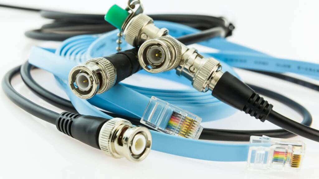
Advanced Ethernet networking sometimes involves coaxial or fiber optic cables. These types of cables carry data in different ways than the standard UTP (Unshielded Twisted Pair) cables like Cat5e or Cat6 cables, requiring other splicing techniques.
Splicing a coaxial cable involves using a specially designed cable stripper to expose the inner conductor. You’ll then crimp on a new coaxial connector. A coaxial coupler can then be used to join the two cables.
As for fiber optic cables, they’re a whole different ball game. These cables carry data in the form of light pulses, and splicing them involves a process called fusion splicing. This process uses heat to fuse or ‘weld’ two fiber optic cables. It’s a delicate and precise process that ensures minimal signal loss and is usually best left to professionals or those who have received appropriate training. It’s highly unlikely you’d have fiber optic cabling inside your home. However, this is high-end business terrain.
Power Over Ethernet (PoE) and Adapters
Sometimes, you can deliver data and power over your Ethernet cable.
This is known as Power Over Ethernet (PoE). It’s typically used for devices like IP cameras or WiFi access points in places where a separate power source isn’t readily available since there’s no suitable electrical wiring.
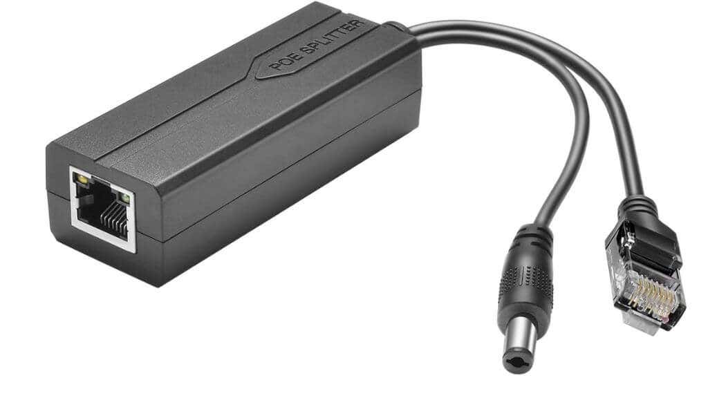
When splicing a PoE cable, it’s crucial to ensure the DC power pins are correctly connected, as they will carry the power to your device. Special PoE adapters are available to simplify this process. Have a look at this PoE pinout guide for exact details.
You can quickly destroy network equipment by accidentally sending power to where it shouldn’t go, so if you have any doubts, it’s better to pay a professional to make up custom-length PoE cables for you.
Wrapping Up
Learning how to splice an Ethernet cable is a handy skill to have, although most people only have the need to do it a handful of times in their lives. Unless you’re going to do a lot of splicing, it’s cheaper to pay for custom-length new cables. Crimping tools and network testers are expensive to justify a one-off DIY project.
If you do decide to attempt this yourself, remember to be safe, respect the color code, and ensure your conductors are appropriately crimped, and you should have a solid Ethernet connection up and running in no time. However, you might want to consider an alternative solution in the form of a Powerline Ethernet Extender.
